Brands
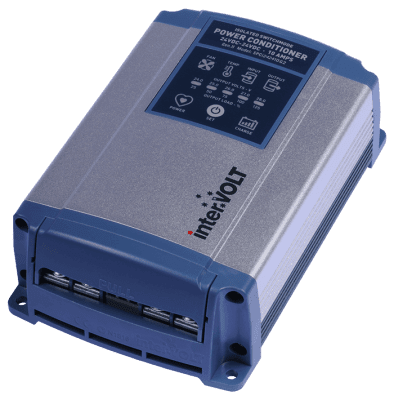
24-24V, 20A G2 POWER CONDITIONER
Overview
The interVOLT's SPCi Power Conditioners Isolated Maxi are known for resolving many of the issues associated with DC Power in vehicles and vessels. They are infact an inverter, stabilizer, isolator and regulator all built into a single package.
The second generation interVOLT SPCi Maxi series isolated power conditioners are the evolution of the original and renowned SPCi models first released in 2003. The GEN II Series is not just a cosmetic ‘makeover’ but rather a complete new product from the ground up. The all new design features complete digital control with a specification second-to-none. Here are just a few of the new features and benefits exclusive to the new range:
- Unique operator interface for control and monitoring
- Galvanically isolated input to output – no common connectivity
- Handy charge mode for charging an auxiliary battery (2 stage)
- High resolution voltage output of less than 0.5% under any load
- Peak efficiency of 92% (better than 90% under most load conditions)
- Remote operator control to turn unit on/off with signal current only
- Multifunction alarm output for fault and pre-emptive warnings
- Temperature and speed controlled internal cooling fan (Vapo bearing)
- Compact design and can be mounted vertically or horizontally
- Heavy duty termination with separate, removable terminal cover
- 24 months warranty (subject to specific terms and conditions)
- High quality assembly featuring marine grade hardware
- Conformally coated printed circuit board assembly (tropicalisation)
| Model | SPCi242420G2 |
| Voltage | 24-24 VDC |
| Rating | 20 Amps |
| Length Overall |
230mm |
| Width Overall |
110mm |
| Height Overall |
55mm |
| Weight | 1150 grams |
12-12 VDC Version:
- Output Voltage (Conditioner Mode) – The voltage output is user selectable in 0.5V increments from 12.0V to 14.0V. The factory default is 13.0V which can be changed at any time.
- Output Voltage (Charger Mode) – Two stage battery charging mode with boost voltage of 14.4V and float of 13.6V.
- Input Voltage – Minimum start-up voltage is 10.5VDC but will allow input dip down to 9V during operation. Maximum input voltage is 16VDC.
24-24 VDC Version:
- Output Voltage (Conditioner Mode) – The voltage output is user selectable in 1.0V increments from 24.0V to 28.0V. The factory default is 26.0V which can be changed at any time.
- Output Voltage (Charger Mode) – Two stage battery charging mode with boost voltage of 28.8V and float of 27.2V.
- Input Voltage – Minimum start-up voltage is 20VDC but will allow input dip down to 17V during operation. Maximum input voltage is 33VDC.
Constant Rating – All units are continuously rated at the published current under 40°C ambient temperature i.e. the 20 Amp version is 20 Amps continuous.
Intermittent Rating – All units have up to a 25% rating over the continuous rating at a maximum of 50% duty cycle for 10 minutes.
Momentary Rating – All units peak at greater than 25% of continuous rating for a period of 5 seconds.
Power Efficiency – Conversion efficiency varies depending upon load but minimum expected is 88% with a peak of 93%. Average is nominally 91%.
Standby Power – With no load connected (idle mode) average current draw is typically 85mA. With remote isolation enabled the average standby current is less than 10mA.
Output ripple – Less than 20mV peak to peak.
Load regulation – Less than 1% variation up to full load rating.
Line regulation – Less than 1% variation subject to voltage input min/max specification.
Environmental considerations – Operating temperature range is -25°C to + 50°C and ideally humidity should not exceed 90%.
Conformity – Conforms to Electro Magnetic Compatibility (EMC) standards as follows: IEC61204?3 for low voltage power supplies, DC output, components EN61000?4?2 to EN61000?4?6 and AS/ NZS CISPR 11 Group 1, Class B.
Construction – Manufactured using corrosion resistant materials throughout, including anodised 6063 aluminium, ABS/ PC plastics and stainless steel hardware. No ferrous materials are used and all PCB assemblies feature conformal coating (tropicalisation).
Safety Devices –
- Shutdown protection with automatic reset for input under voltage, output overload, output short circuit, over temperature and loss of negative reference using purpose built circuitry. All shutdown conditions are output to external source for remote monitoring.
- Internal fuse protection (not user serviceable) for reverse polarity connection and output over voltage condition.
Alarm Devices –
- Pre-emptive warning for impending shutdown due to output overload, input under voltage and over temperature. All alarm conditions are output to external source for remote monitoring.
- Failure warning of internal cooling fan due to obstruction, fault, damage, etc. Condition is output to external source for remote monitoring.
User Interface – the user or operator interface is used to control and monitor the various functions of the SPCi.
- Illuminated icons are used to display fault conditions for internal fan and temperature and various input/output conditions.
- Status bar has dual use, to display operator selected voltage output in set-up mode and to indicate the percentage of load on the output in operation. On power up it will indicate the current voltage setting for a period of 10 seconds.
Auxiliary Connections – for optional control and monitoring functions.
- External Alarm Output – an external signal for remote monitoring of both the pre-emptive and shutdown alarms.
- Remote Switching Input – used to isolate the output from the input with a simple, low current control switch i.e. toggle switch.
Termination – For input/output terminals the SPCi uses high current proprietary terminals with combination M5 fasteners. The control/monitoring terminal is a customized 2 gang Euro block. All in marine grade materials.
Warranty – 24 month
